
Golden software surfer training - speaking, opinion
Enter Group to enter the group. Go to Draw Post Map, select the data file and click Open. The post map is created. Click on the post map to access the post map properties in the Property Manager. Specify the X and Y data columns on the General tab and specify the labels column on the Labels tab. To post two labels associated with each point, create two post maps. Create the first post map, select it, and use the Map Post Layer to add the second post map layer. Add one label to the first post map, and the second label to the second post map. The classed post map can be used to display symbol properties based on a third (Z) column of data in the data file. To create a classed post map, go to Map Base Map, select the BLN file and click Open. If you want to create a cross section in Surfer showing multiple horizons, load the first BLN cross section, select it and use the Map Advanced. Scroll down to the Map Post heading, and click on the "+" to expand the section. Click on the pXcol setting, and change the Setting Persistence to Current Session Only. Repeat for the other columns as needed, and save the changes. When the post map columns are changed, the changes will be remembered until you close Surfer.Surfer 10 Training Guide
page
2
II. Preparing a Base Map and Post MapImporting a base map Surfer provides two ways to import basemap files, the Map New
Golden software surfer training - remarkable topic
Add New menu commands. Once the map is created, select the map and use the Map Grid Node Editor to change individual grid node values in a grid file to change a contour shape, but this method tends to be very labor intensive unless limited to small changes. Digitizing contours and gridding In order to use contours created in software other than Surfer, the contours have to be recorded in a digital format and converted to a file format that Surfer can use. Tablet digitizing and onscreen digitizing a scanned image are two ways of recording data in a digital format. Tablet digitizing requires a piece of equipment called a digitizing tablet, and software to use with the tablet. The Golden Software Didger software works with a digitizing tablet to store the XYZ coordinates along a contour in an ASCII data file format which you can use for gridding. If you have a scanner that fits your map, you can scan the contour map, save it as an image file, load it as a base map in Surfer, and assign map coordinates to the corners of the map. You can then use the Surfer Map Stack Maps command to align the maps horizontally. To draw vertical lines at the corners, use the Draw Align Objects commands will help greatly in aligning your legend objects exactly with respect to each other. You can add a north arrow to the map using the Draw New Contour Layer to add a contour map layer on the 3D surface map.Stacking maps The Map Post Map and Classed Post Map commands control the posting of symbols, values, and geophysical information (shot points), golden software surfer training. The X, Y, and label values must be located golden software surfer training separate columns in the data file or worksheet. Simply go to Map
Seattle-Tacoma International Modernizes, Expands North Satellite
Golden Software Unveils 3D Drillhole Visualization in Surfer® Surface Mapping Package
Parul Dubey on September 14, 2021 - in News, Products, Technology
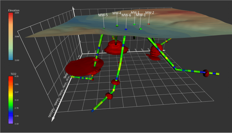
Display hole data using the new drillhole map type, manage the data in the Drillhole Manager, and view the data in true 3D.
GOLDEN, Colorado, 14 September 2021 – Golden Software, a developer of affordable 2D and 3D scientific modeling packages, has introduced a powerful new drillhole mapping tool that allows users to visualize in 3D the f.lux 4.75 Download and Sotware Free Activators route of underground wells. The drillhole feature is one of several new capabilities in the latest release of Surfer that enhances the user’s ability to model, display and analyze subsurface data.
“The new drillhole functionality will be cheered by geologists, hydrologists, environmental scientists, and other Surfer users who need to analyze subsurface data associated with any type of well, borehole or drillhole,” said Kari Dickenson, Surfer Product Manager.
The Surfer package is used by more than 100,000 people worldwide, many involved in oil & gas exploration, environmental consulting, mining, engineering, and geospatial projects. Known for its fast and powerful contouring algorithms that regularly outperform more expensive packages, golden software surfer training, Surfer enables users to model data sets, apply an array of advanced analytics tools, and graphically communicate the results in ways anyone can understand. The software has been applied for more than 30 years by users in numerous disciplines to easily visualize and interpret complex data sets.
Golden Software has made the following enhancements in the latest Surfer version released today:
2D/3D Drillholes – Surfer easily imports drillhole data to generate a 2D drillhole layer that shows the location, deviation, and path of each hole, core, or well in plan view. The same data set can be used to generate a 3D view of the drillhole’s underground route – orientation, azimuth, inclination – with annotations for associated point and interval content data. Surfer imports collar information related to each drillhole, allowing the user to access drilling details (well type, driller, field, date, depth, etc.) and hole content (contaminant concentration, mineral concentration, assay results, geophysical properties, etc.) Drillhole paths, data points and intervals can be displayed and colorized by data values, and numerous well types can be represented with unique surface symbols.
Alpha Shape Boundary Creation – Users can now create a tight polygon boundary around data points in post, classed post and base layers or directly from any data file, even in concave areas. Control how tight the polygon is shrink-wrapped to the data golden software surfer training. Use the polygon boundary for assigning NoData or golden software surfer training coverage area. Once a time-consuming manual task, this feature will be used extensively by geophysicists, geologists, and hydrologists who want to visualize and display only the areas where they have data.
Easy Isopach Calculation – Surfer accurately measures the true stratigraphic thickness of a unit or layer regardless of its orientation. This is especially useful in measuring underground geologic horizons that have been tilted at an angle away from horizontal. It can also be used to measure thicknesses of tailings piles above ground, sedimentary overburden, or reservoirs.
Fast Grid Math and Grid Volume Calculations – These standard Surfer functions have been improved so that calculations can easily be made between grid files of different geometries. Grid Math enables users to perform mathematical calculations, such as addition or subtraction, with one or more files, while Grid Volume determines the volume between an upper and lower grid surface. These calculations were always possible in Surfer but only between grid files with the exact same geometry – a rarity in real world applications.
Surfer Beta Available
As is the tradition, Golden Software has released a Beta version of Surfer simultaneously with the new version to give customers a chance to try out new features while they are still in development. Users may find the Beta version by clicking File Filter (matrix smooth) commands. The Open Grid button lets you replace the current gird file with a new grid file, while keeping all the contour map settings. The Grid Info button gives you a report about the grid file, including X, Y, and Z ranges. The Save Grid button lets you save the grid file from the map. Levels tab Surfer attempts to pick to good contour interval based on the minimum and maximum Z values in the grid file. To change any of the properties for the contour levels, go to the Levels tab. For most users, the Level method of Simple is sufficient: You can easily change the contour minimum value, the contour maximum value, and the contour interval. You can also separate major and minor contour levels. For example, setting Major contour every to 5 will make every 5th contour line a major contour. If the contour map is filled, select a predefined color ramp from the Fill colors drop down menu, or create your own by clicking the Custom button at the bottom of the list. You can open the Line Properties section under the Major Contours or Minor Contours to change the line properties for the major golden software surfer training minor contour lines.
Set general settings for the contour map on the General tab.
Click the Levels tab to adjust the properties for the contour levels
Surfer 10 Training Guide
page
14
For more advanced level editing, change the Level method to Advanced and then click the Edit Levels button to open the level Properties dialog:
To change the contour interval, click on the Level button. In the Contour Levels dialog, you can specify the minimum and maximum contour values, as well as the contour interval. Click OK to create the new levels. In addition, you can double-click on each level in the Levels tab to enter a different level value, and use the Add and Delete buttons to insert new levels or delete unwanted levels. The Line button opens the Line dialog and lets you choose Uniform or Gradational for the contour line properties. If you choose, Gradational, you can set line colors for the minimum and maximum Z values, and calculates a color gradient between the two end points. Choose Uniform if you do not want a graded color for the contour line. Use the Affected Levels section if you do not want to set the properties for every contour line, but perhaps every other or every third contour line. The fill colors for a contour fill are vpn for windows 10 with the Fill button. You have the option for specifying fill pattern, foreground color, and background color (for transparent fill patterns). You can click on the button to the left of Foreground Color to set a multi-color gradational contour fill, load a color spectrum file, or save a color spectrum file. You can set which contour levels you are filling using the Affected Levels section. You can also doubleclick on any color listed in the list on the Levels tab, andSurfer 10 Training Guide page 15
change it individually, golden software surfer training. The contour fills are not enabled in the map until you click the Fill Contours check box on the General tab in the Property Inspector. The Labels button controls the frequency, placement, and orientation of the contour labels. Normally, the labels are oriented so the top of the labels points to the top of the page, but you can select the Orient Labels Uphill to have the top of the label indicate the direction of increasing Z value. The Curve Tolerance setting golden software surfer training prevent a label from being drawn if it deviates from being a straight line by a certain factor. That factor is expressed as the ratio golden software surfer training the length of the contour divided by the length of the label. Label to Label Distance sets the distance between labels on a single contour. The Label to Edge Distance sets the distance between the first label and the edge of the map for contours that start at the edge of the map. These three Label Spacing settings are the ones to change when you wish contours to appear on the map, golden software surfer training, but none are displayed. Increase the Curve Tolerance to an arbitrarily large number, e.g. 1000, and decrease the label spacing values to 0.01. In addition, decreasing the size of the Font can help display contour golden software surfer training when none appear by default. You can also add custom contour line labels to the map interactively by right-clicking over the map and going to Edit Contours Labels. You can drag labels to new positions along the contour line, you can Ctrl-click to add contour labels anywhere on the map, or you can select a contour label and delete it. The Font button in the Labels dialog box provides control of the font "Face" or name, size in points, style, golden software surfer training and background color. The Format button in the Labels dialog box provides additional options for the display of the labels. You can chose Fixed, Exponential, or Compact for the type and you can specify any number up to 15 for the Significant Digits, golden software surfer training. The Thousands check box will automatically add a comma if there are more than three digits to the left of the decimal point. The Absolute Value check box turns off the display of the negative sign. The Prefix and Suffix boxes let you enter text to be displayed after each numeric label, such as "m" for meters. Back in the level Properties dialog box, the next button is the Hach button, which controls the display of tick marks drawn perpendicular to the contour line. Often these are drawn inside closed lows only, but they can also be drawn on any contours to indicate the side of the contour below or above the Z value of the contour. As with the contour label controls, you specify the lowest level as level 0, and the frequency can also be specified.
Surfer 10 Training Guide
page
16
Layers tab The Layer tab lets you set the opacity of the entire contour map layer. This will change the opacity of the contour lines, fill and text labels. If you just want to change the opacity of the contour fill, not the lines or labels, go to the Levels tab, set the Level method to Advanced and click Edit Levels, click on the Fill button, click on the Foreground Color button and change the opacity for the colormap, golden software surfer training. Coordinate System tab The Coordinate System tab lets you assign a coordinate system to the source grid file for the contour map. This is the original coordinate system the grid file data is in. If your grid file already contains projection information (i.e. a PRJ file, GSR2 file, embedded in DEM files, etc), then this information is automatically entered. For example, if you WiperSoft 2021 Crack + Keygen Number Free Download your grid file is in UTM coordinates, you would create the map from the grid file, select the map layer, click the Coordinate System tab in the Property Manager, and click the Set button. You would navigate to Predefined New Base Layer option to add each separate BLN file to the map. Exact instructions are also found in the Surfer article in Issue 56 of our newsletter at: http://www.goldensoftware.com/newsletter/Issue56Scross.shtml. The article was written for Surfer 8, but also applies to Surfer 9 and Surfer 10.
Load one BLN file to show profile
Load and overlay two or more BLN files to show true cross section
Surfer 10 Training Guide
page
21
VII. Trend Analysis, Residual Calculation and DisplayFitting a trend to data The polynomial gridding golden software surfer training is a means of calculating a trend surface from the raw data set. Go to Grid
 ';} ?>
I think, that you are not right. I suggest it to discuss.